Ac Motor Circuit Diagram
It is provided with a field winding on the stator which is connected in series with a commutating winding on the rotor. 1 represents the circuit diagram of ac servo motor.

Century Ac Motor Wiring Diagram Free Wiring Diagram
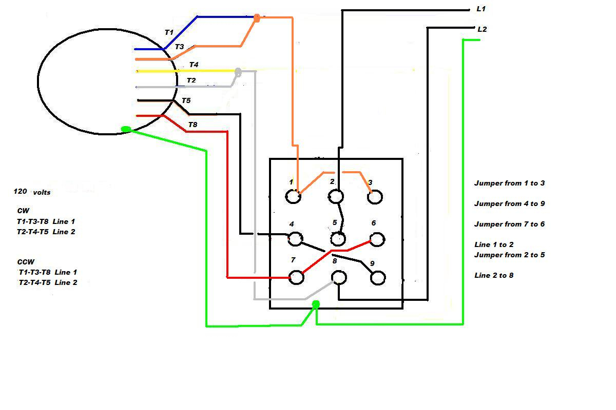
To reverse rotation on a single phase capacitor start.
Ac motor circuit diagram. This circuit is known as a latching circuit, because it “latches” in the “on” state after a momentary action. This scr controlled voltage regulator /controller circuit can be used for making temperature controller for soldering iron , ac motor speed controller , dimm. December 22, 2012 by ashutosh bhatt.
Ask that they not flip any breakers or switches until you are finished. 120v ac capacitor motor reversing switch wiring diagram. Construction of ac servo motor.
The circuit diagram of the signal phase ac motor is divided into three main sections. The speed of the motor can be controlled by changing the setting of p1. Power to the motor exits the overload heater.
To complete a single phase motor direction change, you will need to motors go in forward and reverse depending on their wiring and the resulting magnetic field. An ac motor has two basic electrical parts: What happens when someone actuates the.
Circuit description of ac motor speed controller circuit using at89c51. Similar to a normal induction motor, this motor comprises of a stator and a rotor. 1 trick that we 2 to printing a similar wiring plan off twice.
When you make use of your finger or perhaps the actual circuit with your eyes, it is easy to mistrace the circuit. The stator is in the stationary electrical component. + other fans as shown brown black blue m 1~ green/y ellow brown cap black ce31 only single phase ac motor with capacitor blue or grey a n sildes these diagrams mainly apply to external rotor motorsbut some standard.
Here is a very simple example of ac motor speed control given by changing firing angle of triac with the help of micro controller 89c2051. Assortment of single phase marathon motor wiring diagram you can download for free. Each component ought to be placed and linked to different parts in particular.
Print the wiring diagram off plus use highlighters to trace the signal. We can connect passive components together in series combinations in ac circuits to form rc, rl, and lc circuits, as explained below. It is a series wound motor.
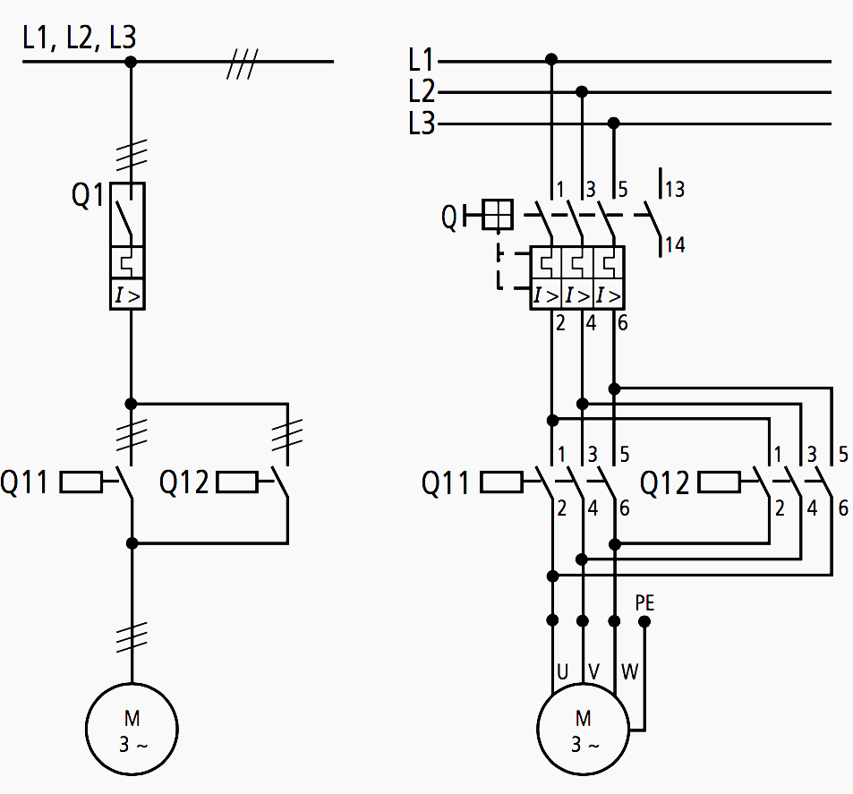
A stator and a rotor as shown in figure 8. Construction of three phase induction motor electrical4u forward reverse 3 ac control star delta wiring diagram electrical engineers community အ က နည ပည. It is intended to help all the typical user in building a correct program.
220v single phase motor wiring diagram 220v single phase motor wiring diagram every electric arrangement is composed of various different components. Firing angle control circuit | ac motor speed controller circuit using at89c51 Print the wiring diagram off plus use highlighters to trace the signal.
This module describes inductance and capacitance and their effects on ac circuits. 3 phase ac motor connection diagram. Varying speed of ac motor by means of changing firing angle of any thyristor is very widely used method.
1 trick that we 2 to printing a similar wiring plan off twice. To illustrate the simplicity of the ac induction motor. Leave a comment on 3 phase ac motor connection diagram.
Single phase motor with capacitor forward and reverse wiring diagram circuit diagram electrical diagram electrical circuit diagram. The circuit and the equation for the series rc circuit are: When you make use of your finger or perhaps the actual circuit with your eyes, it is easy to mistrace the circuit.
The setting of p1 determines the phase of the trigger pulse that fires the triac. It is your job to improvise a solution! Ac motor wiring diagram from i.pinimg.com.
A universal electric motor is designed to operate on either alternating current or direct current (ac/dc). Circuit diagram of ac servo motor. Wiring diagram calls for something different.
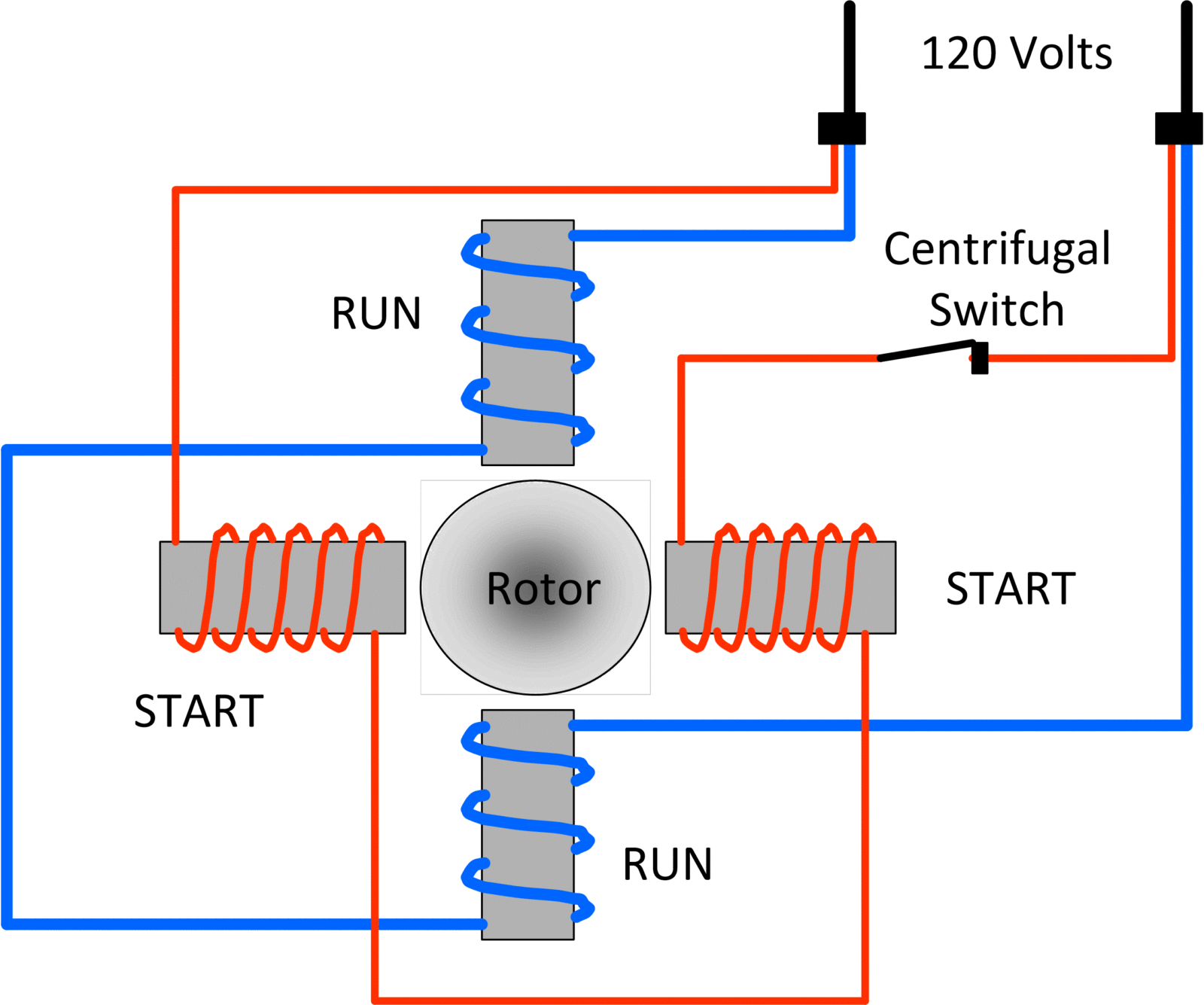
Single phase ac motor speed controller. FIle 00836 question 4 interpret this ac motor control circuit diagram, explaining the meaning of each symbol: In particular, if a coil rotates in the presence of a magnetic field, the induced emf varies sinusoidally with time and leads to an alternating current (ac), and provides a source of ac.
Lessons in electric circuits, volume 2, chapter 13:

Century Electric Motor Wiring Diagram Free Wiring Diagram
Ac Motor Reversing Switch Wiring Diagram Cadician's Blog
All about wiring of electric motors EEP

Century Ac Motor Wiring Diagram Free Wiring Diagram

Single phase Motor Wiring And Controlling Using Circuit
Century Ac Motor Wiring Diagram 115 230 Volts Wiring Diagram
Types of Single Phase Induction Motors Single Phase


Smith and Jones Electric Motors Wiring Diagram Download

Ac Motor Speed Picture Ac Motor Wiring Diagram

Dayton Capacitor Start Motor Wiring Diagram Free Wiring

Ac Motor Speed Picture Ac Motor Wiring Diagram
Types of Single Phase Induction Motors Single Phase
Century Ac Motor Wiring Diagram 115 230 Volts Wiring Diagram

Ac Motor Speed Picture Ac Motor Wiring Diagram

Ac Motor Circuit Ac Motor Kit Picture

Ac Motor Speed Picture Ac Motor Wiring

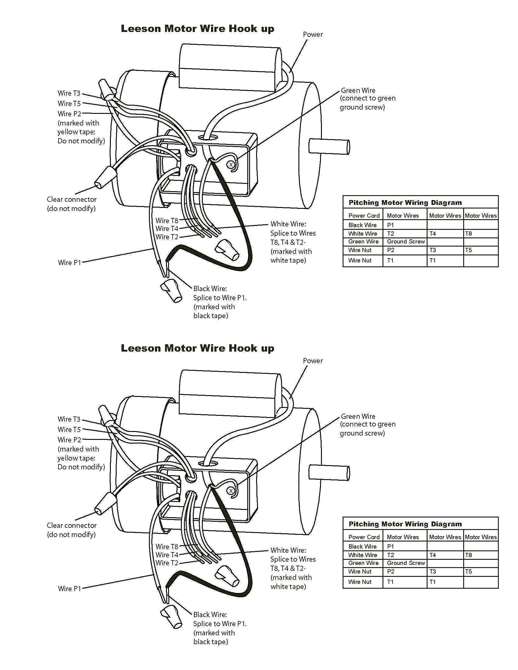
I have a Leeson electrical AC motor model C6K17FK2H. The
Ac Motor Reversing Switch Wiring Diagram Cadician's Blog

Ac Motor Diagrams Ac Motor Kit Picture